Information and binary coding
For humans, information can be pictures, symbols, words, sounds, movements,
and more. A typical computer has a keyboard and mouse so that words and
movements can be sent to the processor as information. The information
must be converted into electrical off-on (``0 and 1'')
pulses that travel on the bus
and arrive to the processor, which
can save them in primary storage.
It is premature to study precisely how numbers and symbols can be
represented as off-on (0-1) pulses, but here is review of base-2 (binary)
coding of numbers, which is the concept upon which computer information
is based:
number   binary coding
 0        0000
 1        0001
 2        0010
 3        0011
 4        0100
 5        0101
 6        0110
 7        0111
 8        1000
    ...
14        1110
15        1111
and so on. It is possible to do arithmetic in base two, e.g.
3+5 is written:
 0011
+0101
-----
 1000
The addition works like normal (base-10) arithmetic, where
1 + 1 = 10 (0 with a carry of 1). Subtraction, multiplication, etc.,
work this way, too, and it is possible to wire an electrical circuit
that mechancially does the addition of the 0s and 1s.
Indeed, a processor uses such a wiring, which operates on
binary numbers held in
registers, where a register is
a sequence of
bits (electronic ``flip-flops'' each of which
can remember a 0 or 1).
Here is a picture of an 8-bit
register that holds the number 9:
+--+--+--+--+--+--+--+--+
| 0| 0| 0| 0| 1| 0| 0| 1|
+--+--+--+--+--+--+--+--+
A processor has multiple such registers, and it can compute 3+5
by placing 3 (0000 0011) and
5 (0000 0101) into two registers and then using the wiring between
the registers to compute the sum, which might be saved in a third
register.
A typical, modern register has 32 bits, called a fullword.
Such a register can store a value in the approximate range of
-2 billion to +2 billion.
When an answer, like 3+5 = 8, is computed, the processor might
copy the answer to primary storage to save it for later use.
Later, the processor can copy the number from storage
back into a register and do more arithmetic with it.
Central processing unit
The processor is truly
the computer --- it is wired
to compute arithmetic and related operations on numbers that it
can hold in its data registers.
A processor is also called a
Central Processing Unit (CPU).
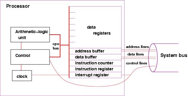
Here is a
simplistic picture of the parts of a processor:
-
The data registers hold numbers for computation, as noted earlier.
-
There is a simple clock --- a pulse generator ---
that helps the Control Unit do instructions in proper time steps.
-
The arithmetic-logic unit (ALU) holds the wiring for doing arithmetic
on the numbers held in the data registers.
(Review the addition example above.)
-
The control unit holds wiring that triggers the arithmetic
operations in the ALU. How does the control unit know to request an
addition or a subtraction? The answer is: it obtains instructions,
one at a time, that have been stored in primary storage.
-
The instruction counter is a register that tells the
control unit where to find the instruction that it must do.
(The details will be explained shortly.)
-
The instruction
register is where the instruction can be copied and held
for study by the control unit,
-
The address buffer and data buffer are two registers that
are a ``drop-off'' point when the
processor wishes to copy information from a register to primary storage
(or read information from primary storage to a register). We study
them later.
-
The interrupt register is studied much later.
A processor's speed
is measured in Hertz (a kind of vibration speed) and is
literally the speed of the computer's internal clock;
the larger the Hertz number, the faster the processor.
Primary storage
Primary storage (also called
random-access memory --- RAM)
is literally a long sequence of fullwords, also called
cells, where numbers can
be saved for later use by the processor.
(Recall that a fullword
is 32 bits). Here is a simplistic picture:
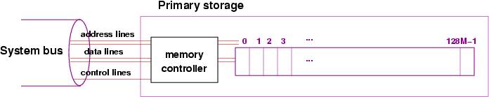
The picture shows that each fullword (cell) is numbered by a unique
address
(analogous to street addresses for houses), so that information transferred
from the processor can be saved at a specific cell's address and can be later
retrieved by referring to that same address.
The picture shows an additional component, the memory controller,
which is itself a primitive processor that can quickly find addresses
and copy information stored in the addresses to/from the system bus.
This works faster than if the processor did
the work of reaching into storage to extract information.
When a number is copied from the processor into storage, we say it is
written; when it is copied from storage into the processor,
we say it is read.
As the diagram suggests, the address lines in the system bus
are wires that transfer the bits that form the address of the cell
in storage that must be read or written (the address is transmitted from
the processor's address buffer --- see the previous section);
the data lines
are wires that transfer the information between the processor's
data buffer and the cell in storage;
and the control lines transmit whether the
operation is a read or write to primary storage.
The tradition is to measure size of storage in bytes,
where 8 bits equal one
byte, and 4 bytes equal one fullword. The larger the number, the larger the
storage.
Stored programs
In the 1950's, John von Neumann realized that primary storage could hold
not only numbers, but patterns of bits that represented
instructions that could tell the processor (actually, tell
the processor's control unit) what to do.
A sequence of instructions was
called a program, and this was the beginning of stored-program,
general purpose
computers, where each time a computer was started, it could
receive a new program in storage, which told the processor what
computations to do.
Here is a simplistic example of a stored program that tells the
processor to compute the sum of three numbers held in primary storage
at addresses, 64, 65, and 66 and place the result into the cell
at address 67:
LOAD (read) the number at storage address 64 into data register 1
LOAD the number at storage address 65 into data register 2
ADD register 1 to register 2 and leave the sum in register 2
LOAD the number at address 66 to register 1
ADD register 1 to register 2 and leave the sum in register 2
STORE (write) the value in register 2 to storage address 67
instructions like LOAD, ADD, and STORE can be represented as bit patterns
that are copied into the processor's instruction register.
Here is a simple coding of the six-instruction program, which
is situated at addresses 1-6 of primary storage
(and the numbers are at 64-66).
The instructions are coded in bit patterns, and we assume
that LOAD is 1001, ADD is 1010, and STORE is 1011.
Registers 1 and 2 are 0001 and 0010.
Storage addresses 64 -- 67 are of course
0100 0000 to 0100 0011.
The format of each instruction is: IIII RRRR DDDD DDDD,
where IIII is the coding that states the operation required,
RRRR is the coding
of which data register to use, and DDDD DDDD is the data, which is
either a storage address or another register number.
PRIMARY STORAGE

address: contents
-------  --------
0:  ...
1:  1001 0001 0100 0000
2:  1001 0010 0100 0001
3:  1010 0010 0000 0001
4:  1001 0001 0100 0010
5:  1010 0010 0000 0001
6:  1011 0010 0100 0011
7:  ...
...
64: 0000 0000 0000 0100
65: 0000 0000 0000 0011
66: 0000 0000 0000 0001
67: ...
...
(Note: I have shortened the instructions to 16 bits, rather than use
32, because I got tired typing lots of zeros!)
The example is a contrived, but it should convince
you that it is indeed possible to write
instructions in terms of binary codings that a control unit
can decode, disassemble, and execute.
It is painful for humans to read and write such codings,
which are called machine language,
and there are abbreviations, called assembly language,
that use text forms. Here is a sample assembly-language version of the
addition program:
LOAD R1 64
LOAD R2 65
ADD R2 R1
LOAD R1 66
ADD R2 R1
STORE R2 67
Instruction cycle
The
instructor cycle are the actions taken by the processor
to execute one instruction.
Each time the processor's clock pulses (ticks) the
control unit does these steps:
(actually, modern processors do multiple instruction cycles
for each clock pulse)
-
uses the number in the instruction counter to fetch
an instruction from primary storage and copy it into the instruction register
-
reads the pattern of bits in the instruction register and
decodes the instruction
-
based on the decoding, tells the ALU to
execute the instruction, which means that the ALU
manipulates the registers accordingly.
-
There is a fourth step in the instruction cycle, an
interrupt check, that we study later.
Of course, the control unit is not alive, and it does not ``read'' or
``tell'' anything to anyone, but there is wiring between
electrical components that propagate
electrical 0-1 signals --- a kind of falling domino game---
that gives the appearance of conscious execution.
Here is a small example. Say that the clock has ``ticked''
(pulsed), and the instruction register holds 3.
Say that address 3 in primary storage holds the coding of
the instruction, ADD R2 R1.
The instruction cycle might go like this:
-
Fetch:
Consult the instruction counter; see it holds 0000 0011, that is, 3.
Signal the memory controller to copy the contents of the cell
at address 0000 0010
into the data buffer.
When the instruction
arrives, copy it from the data buffer into the instruction register.
Increment the instruction counter to 4 (that is, 0000 0100).
-
Decode:
Read the first (leading or high-order) bits and see that they indicate
an ADD. Extract the bits that state the two registers to be added, here,
R2 and R1.
-
Execute:
Signal the ALU to add the values in registers 1 and
2 and place the result in register 2.
The previous description reads a bit tediously. This is OK,
because the processor is incredibly fast. Nonetheless, modern
processors can be made even faster, because while the ALU is doing
the execution step, the controller can start the fetch-and-decode
steps of the
next instruction cycle. This form of
speedup is called
pipelining and is a topic intensively
studied in computer architecture.
The forms of instruction that the processor can execute are called the
instruction set.
There are these forms of instructions found in an instruction set:
-
data transfer between storage and registers (LOAD and STORE)
-
arithmetic and logic (ADD, SUBTRACT, ...)
-
control (test and branch) (the ALU perhaps resets the instruction counter)
-
input and output (the ALU sends a request on the system bus
to an input/output device
to read or write new information into storage)
Even small examples are painful to write in assembly language,
and people quickly developed simpler notations that could be
mechanically converted to assembly (which could itself be mechanically
converted into base-2 codings).
FORTRAN (formula translator language)
is a famous example, developed in the
1950's by John Backus.
When a human writes a program using FORTRAN, she writes a set
of mathematical equations that the computer executes.
Instead of using specific numerical storage addresses, names from
algebra (``variable names''), like x and y,
can be used instead.
Here is an example, coded in FORTRAN, that places a value in a
storage cell, named x, and then divides it by 2, saving the result again
in the same cell:
x = 3.14159
x = x / 2
And here is an example that divides x by y, saving the answer in x's
cell,
provided that y has a non-zero value:
if ( y .NEQ. 0 ) x = x / y
(read this as ``if y not-equal-to 0, then compute x = x / y'')
With some work, one can write a program that mechanically
translates FORTRAN programs into (long) sequences of machine code;
such a program is called a compiler.
There is another ``translation program,'' called an interpreter,
which does not convert a program to machine code, but instead
reads a program one line at a time and tells the processor to execute
``pre-fabricated'' sequences of instructions that match the program's
lines. These concepts are developed in another lecture.
Languages like FORTRAN (and COBOL and LISP and C and Java and ...)
are called high-level programming languages.
Secondary storage: disks
The previous section stated that programs and numbers can be saved
in primary storage. But there is a limited amount of primary storage,
and it is used to hold the program that the computer
executes now. Programs and information that are saved for
later use can be copied to
secondary storage,
such as the internal disk that is common to almost all computers.
Although it looks and operates differently than primary storage,
it is perfectly fine to think of disk storage (and other forms of
secondary storage, like a memory key or a CD), as a variant
of primary storage, connected to the processor by means of the system
bus, using its own controller to help read and write information.
The main distinction is that secondary storage is cheaper (to buy)
than primary storage, but it is slower to read and write information
to and from it.
A typical computer uses disk secondary storage to hold a wide variety
of programs that can be copied into primary storage for execution,
as requested by the user. Secondary storage is also used to
archive data files.
Secondary-storage devices are activated when the processor executes
a READ or WRITE instruction. These instructions are not as simple to do
as the LOAD and STORE instructions, because the secondary-storage
devices are so slow, and the processor should not waste time,
doing nothing, waiting for the device to finish its work.
The solution is: The processor makes the request for a read or
write and then proceeds to do other work.
Consider how a processor might
execute a WRITE instruction to the disk; here is how the
instruction cycle might go:
-
Fetch:
The control unit obtains the instruction from primary storage and
places it in the instruction register, as usual.
-
Decode:
The control unit reads the instruction and determines that it is a WRITE.
It extracts that name of the device to be read (the disk),
it extracts the address on the device where the information should
be written, and it extracts the name of the register than holds the
information to be written.
-
Execute:
The control unit writes the address and data to the disk's
address buffer and data buffer, which are two
fullwords in primary storage. When these writes are finished, the controller
signals the disk along the control lines of the system bus that there
is information waiting for it in primary storage.
Now that the processor has initiated the disk-write, it proceeds to the
next instruction to execute, and at the same time, the disk starts
to spin, its own controller does a read of primary storage for the
address and data information saved there, and finally, the data
is written from primary storage to the disk.
Each secondary-storage device has its own ``buffers'' reserved for it
in primary storage --- this is simpler than wiring the processor
for buffers for each possible storage device.
An important ``secondary storage'' device (actually, it is an output device!) is the
computer's display. A typical display is a huge grid of pixels (colored dots),
each of which is defined by a trio of red-green-blue numerical values.
The display has a huge buffer in primary storage, where there is one
(or more) cell that
describes the color of each pixel.
A write instruction executed by the processor causes
the display's buffer to be altered at the appropriate cells,
and the display's controller (called the ``video controller'')
reads the information in the buffer and
copies its contents to the display, thus repainting the display.
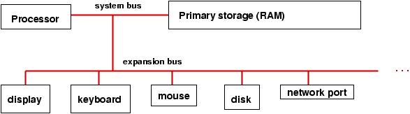
To summarize,
here is a picture of a computer with
buffers reserved for input/output devices in primary storage:
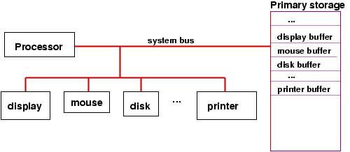
It is important to see in the picture that (the controllers in) the various
storage devices can use the system bus to read/write from primary storage
without bothering the processor. So, input and output
can proceed at the same time that the processor executes instructions.
When a computer is connected to an outside network, the network
can also be considered a kind of secondary-storage device that
responds to read and write instructions, but the format of the
reads and writes is far more complex --- they must include
the address of the destination computer, the kind of data
transmitted, the stage of interaction that is being done, etc.
So, there are standardized patterns of bits,
called protocols,
that must be transmitted
as ``reads'' and ``writes'' from the processor to the system bus
to the port to the network. To accomplish a complete read or
write, there might well be multiple transmissions from
processor to bus to port to network.
The design of
protocols is a crucial issue
to computer networks.
Interrupts
The previous section noted that a processor should not wait
for a secondary-storage device to complete a write operation.
But what if the processor asks the device to perform a read operation,
how will the processor know when the information
has been successfully read and deposited into the device's buffer
in storage?
Here is a second, similar situation: A human presses the mouse's button,
demanding attention from the processor (perhaps to start or stop
a program or to provide input to the program that the
processor is executing). How is the processor signalled about the
mouse click?
To handle these situations, all processors are wired for
interruption of their normal executions. Such an interruption
is called an interrupt.
Recall the standard execution cycle:
-
fetch
-
decode
-
execute
-
check for interrupts
and recall the extra register, the
interrupt register,
that is embedded in the processor:
The interrupt register is connected to the
the system bus, so that when a secondary storage
device has completed an action, it signals the control unit by
setting to 1 one of the bits in the interrupt register.
Now,
we can explain the final step of the execution cycle, the check for
interrupts: After the execution step, the control unit examines
the contents of the interrupt register, checking to see if any
bit in the register is set to 1. If all bits are 0, then no
device has completed an action, so the processor can start a
new instruction.
But if a bit is set to 1, then there is an interrupt ---
the processor must pause its
execution and do whatever instructions are needed:
For example, perhaps the user has pressed the mouse button.
The device controller for the mouse sends a signal on the
system bus to set to 1 the bit for a ``mouse interrupt''
in the interrupt register.
When the control unit examines the interrupt register at the
end of its current execution cycle, it sees
that the bit for the mouse is set to 1. So, it resets the
bit to 0 and resets the instruction counter to the address
of the program that must be executed whenever the mouse button is pressed.
Once the mouse-button program finishes, the processor can resume
the work it was doing.
The mouse-button program is called an interrupt handler.
The previous story skipped a lot of details: Where does the processor
find the interrupt-handler program
for the mouse?
What happens to the information resting in the registers
if we must pause execution and start a new program,
namely, the interrupt handler? What if more
than one interrupt bit is set? What if a new interrupt bit gets
set while the processor is executing the mouse-button program?
Some of the answers are a bit
complex. Based on this picture, we can provide simplistic
answers:
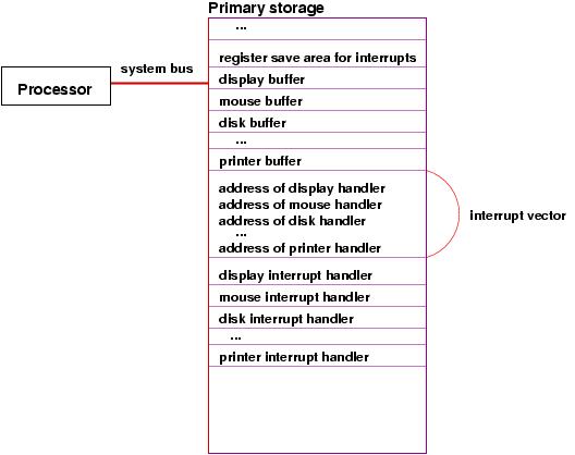
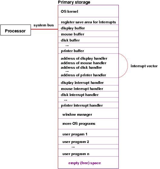
Cells in primary storage hold the addresses
of the starting instructions for each of the interrupt handlers for
the devices. The sequence of addresses is called
an
interrupt vector. The processor finds the address
of the needed interrupt handler from the interrupt vector.
Before the processor starts executing an interrupt handler,
it must copy the current values in all its registers
to a register-save area
in primary storage. When the interrupt handler is finished,
the values in the register-save area are copied back into the
registers in the processor, so that the processor can resume
what it was doing before the interrupt.
The case of multiple interrupts is not covered here, but the basic
idea is that an executing interrupt handler can itself be interrupted
and its own registers can be saved.
The Operating System
The previous narrative shows that the computer's operation
is getting complicated --- there are special storage areas,
special programs, etc. It is useful to have a startup program
that creates these special items and
manages everything.
The startup- and manager-program is the operating system.
When the computer is first started, the operating system is the
program that executes first. As noted, it initializes the computer's
storage as well as the controllers for the various
devices.
The interrupt handlers just discussed as considered parts of the
operating system.
In addition, the operating system helps the processor execute
multiple programs ``simultaneously'' by executing each program
a bit at a time. This technique, which is studied carefully
in another lecture, is crucial so that a human user can start and use, say,
a web browser and a text editor, at the same time.
The operating system is especially helpful at managing one particular
output device --- the computer's display.
The operating system includes a program called the window manager,
which when executed, paints and repaints as needed
the pixels
in the display. The window manager must be executing ``all the time,''
even while the human user starts programs like a web browser, text
editor, etc.
The operating system lets the window manager repaint the display
in stages: when the
window-manager program repaints the display, it must execute
a sequence of
WRITE instructions. When the processor executes one of the
WRITE instructions, this triggers the display's
controller to paint part of the display. When the display controller
finishes painting the part, it sets a bit in the interrupt
register so that the interrupt
handler for the display can execute and tell the processor to
restart the window manager and continue repainting
the display. In this way, the window manager is
executing ``all the time,'' in starts and stops.
Here is a revised picture of the computer's storage, which
shows the inclusion of the operating system (``OS'') and the division
of the remaining storage for the multiple user programs that are
executing: